ICOM Internal Breakouts
Last updated on 2024-03-15
Why
MSF uses a lot of ICOM IC-F5000 series radios in the field. These are VHF FM radios that can be upgraded with an internal module to work as a dPMR or NXDN radios.
We wanted to explore the capabilities of these internal expansion connectors and see if we could use them to interface with other devices (for example an FSK modulator for pagers).
In order to do some prototyping, and after trying to solder tiny wires on the tiny pads of the PCB, I decided to design a breakout board that would make it easier to interface with the radio.
After finding the correct connectors, I designed a PCB that would fit in the radio and expose the internal connectors to more standard 2.54mm pitch headers.
The connectors for J1 and J2 are the same, but the pinout is different as J2 is intended for DSPs like the UT-126H.
I also added a connector for the internal GPS connector (J3), as the radio can transmit GPS positions with an external or internal GPS receiver, but I've never seen the internal GPS receiver and wanted to see if it was feasible.
Some time later after ordering everything
After the parts arrived and I assembled the PCBs, I discovered that J3 was a 1mm pitch connector and not a 0.8mm, it can fit with a bit of wiggling but still, womp womp... This is not a big deal as J3 can't really be used with the ICOM Japan firmware the radios are running, so UART for the internal GPS module will have to come from J1 !
After some tinkering with ManoelDaSilva, AlexandreRouma and Bastien Cabay with a few M17 modems, we discovered that the IC-F5000 series radios and the IC-F3162T portable radios work quite nicely with M17 ! The audio quality is great (even though with the janky wiring there is some RFI), you can find a video with the IC-F5060 here and with the IC-F3162T here.
The madlads from the M17 project even made a micro M17 modem that entirely fits in the radio.
Pinouts
These are the pinouts of J1 and J2 that can be found on the service manual of the radio (available online).
J1
           ┌─────╮*
      NC   │40  1│   NC
     GND   │39  2│   GND
     +5V   │38  3│   PTTI
     VCC   │37  4│   PTTO
      NC   │36  5│   MCOT
   MMUTI   │35  6│   NC
    AFON   │34  7│   MCIN
    BEPO   │33  8│   NC
    RMUT   │32  9│   NC
    DISC   │31 10│   NC
   AFOUT   │30 11│   NC
      NC   │29 12│   BUSY
     REM   │28 13│   SIGO
     CCS   │27 14│   OPT1/RxD
    CIRQ   │26 15│   OPT2/TxD
      NC   │25 16│   OPT3
     CSO   │24 17│   GND
     CSI   │23 18│   OPV3
     CCK   │22 19│   OPV2
      NC   │21 20│   OPV1
           └─────╯
J2
           ┌─────╮*
     DIF   │40  1│   DIF
     GND   │39  2│   GND
     +5V   │38  3│   NC
      8V   │37  4│   NC
      NC   │36  5│   NC
      NC   │35  6│   DMO
      NC   │34  7│   NC
      NC   │33  8│   DMI
      NC   │32  9│   NC
    DISC   │31 10│   VREF
      NC   │30 11│   NC
    DAFO   │29 12│   NC
      NC   │28 13│   NC
     CCS   │27 14│   OPT1 (DPDN)
    CIRQ   │26 15│   OPT2 (DRES)
      NC   │25 16│   OPT3 (DRES)
     CSO   │24 17│   GND
     CSI   │23 18│   NC
     CCK   │22 19│   GND
     GND   │21 20│   GND
           └─────╯
BOM
- Mating connectors for J1 and J2 : Panasonic P5 Series P5K AXK640347YG
- Mating connector for 0.8mm pitch GPS connector : Samtec FTE-105-01-G-DV
- 4x 1x10 2.54mm pitch headers
- 1x 2x5 2.54mm pitch header
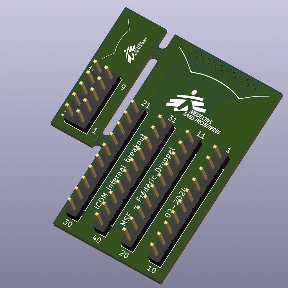
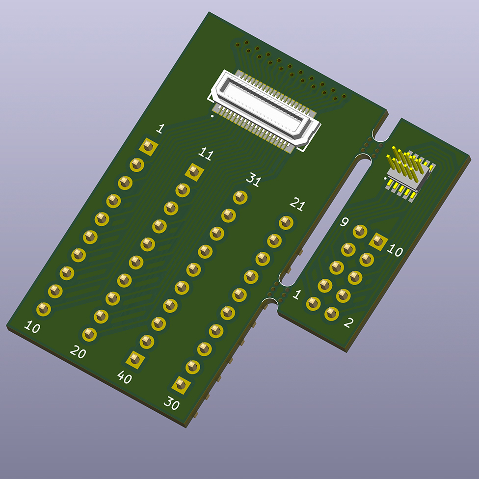
PCBs
Here are some 3D renders of the PCBs :
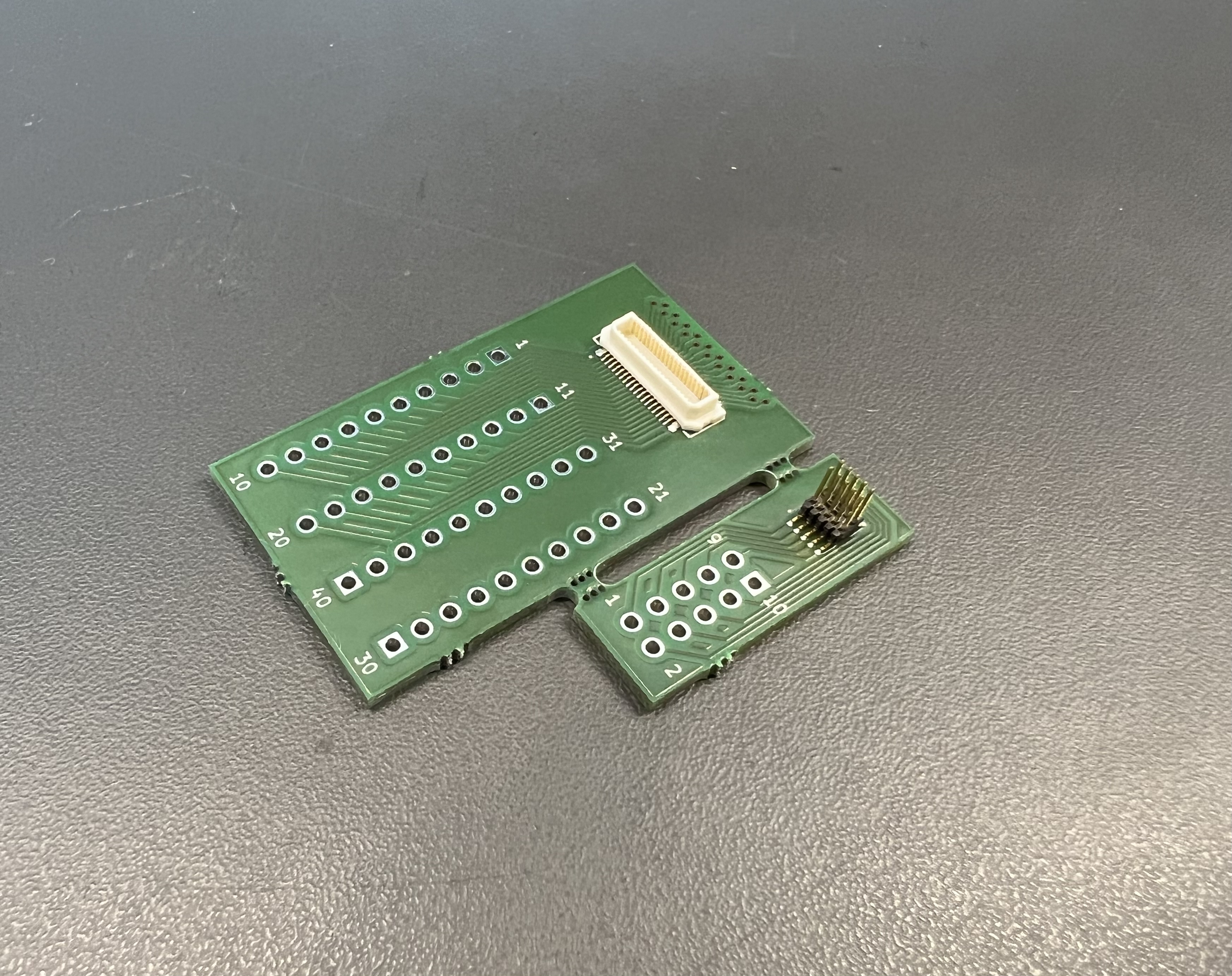
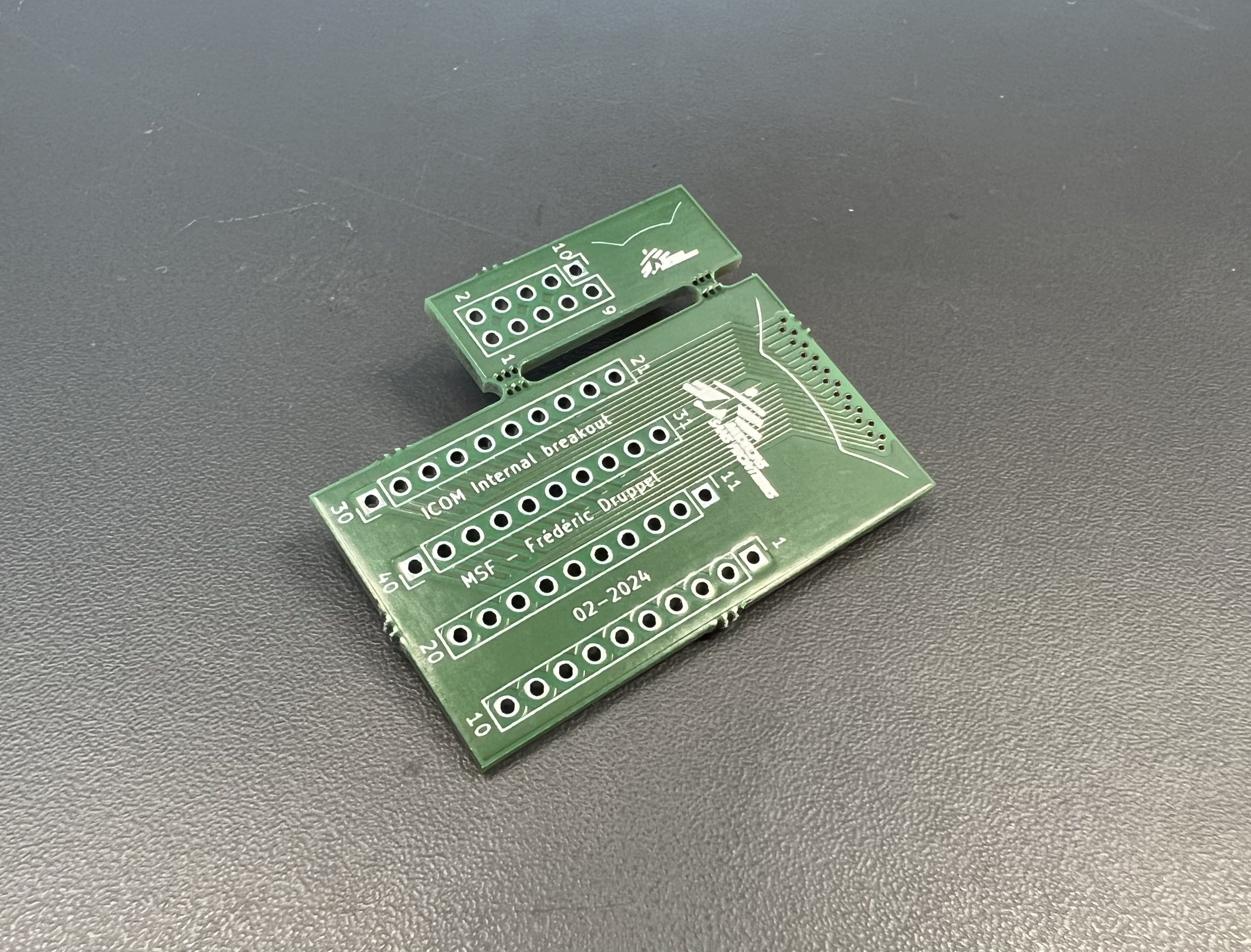
And here is one assembled ! :
Downloads & Links
Note : Gerber files exported with default settings, you might want to re-export from KiCAD depending on your PCB manufacturer